In AutoTRAX DEX you can add graphical lines to both schematics and PCBs.
To set the Line Styles before adding lines, use the Default Graphics Settings
1.To add a line, click on the line button in the Add→Shapes menu.
2.Now move the mouse to where you want to start the line then:
a.Left-click when the start cross is where you want to start of the line to be or
b.press the Enter key followed by the X value, Enter/Space/Tab key, the Y value, and then Enter/Space/Tab to exactly place the starting point.
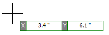
Start point cursor and input boxes
3.Now as you move the mouse you will see the line being drawn and the end point will follow the cursor. If snap is enabled, both the start and the end points will snap to the grid. At any time you can turn snap on and off by pressing the ‘s’ key. As you move the mouse, the length and angle of the line displayed. Left click to define the line's end point or press the Enter key followed by the length, Enter, the angle, and Enter to exactly define the end point of line. Note that as you move the end of the line, if smart pan is enabled, the viewport will automatically pan so the end point is always visible. If possible, the original view will be restored.
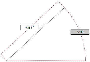
End point cursor and input boxes
To turn smart-pan on or off, click on the smart-pan button on the status bar.
If you have Auto-repeat commands enabled, then you will be prompted to enter the start point for another line. To cancel adding more lines press either the ESC key or right-click and select cancel from the context menu.
Alternately, you can create a line by left-clicking and holding at the location for the start of the line, moving to the end location for the line and releasing the left button. The line is then added to your design.