Whats New for 2025
December
Monday 29 December 2025
Adding Copper Pours Filling the PCB
This should save you a lot of time if you want to add a copper pour to either side of the PCB and have the copper pour fill the PCB.

New Add Button

Adding Copper Pours Filling the PCB
Thursday 17 December 2025
 Bug Fix
Fix for layer errors opening old designs. (older than probably 3 years).
Saturday 6 December 2025
Bug FixRounded copper pour rectangles not filled correctly. Rounding ignored.
Monday 1 December 2025

Navigator Panel
Bug FixNavigator selects footprint for selected symbol when switching tab from schematic to PCB, likewise
Navigator selects symbol for selected footprint when switching tab from PCB to schematic.
November
Wednesday 26 November 2025
Windows on ARM64
DEX now works on ARM64 processors. e.g. Microsoft Surface Pro etc.
The installer uses NGEN.
"Ngen arm64" refers to the Native Generator, a tool that creates native machine code for ARM64 processors from .NET assemblies. This process is used to improve the startup performance of applications by pre-compiling the code, so it doesn't need to be compiled to native code at runtime by the Just-In-Time (JIT) compiler. For example, recent versions of the .NET NGen tool support generating native images for ARM64 systems.
How it works
•Initial compilation: When a .NET application is built, the code is compiled into an Intermediate Language (IL) that is platform-agnostic.
•Runtime compilation: At runtime, the .NET Just-In-Time (JIT) compiler converts the IL into native machine code for the specific CPU architecture the application is running on (e.g., ARM64 or x64).
•NGEN optimization: NGen runs ahead of time to pre-compile the IL into native ARM64 code. This native image is then stored on disk.
•Faster execution: When the application starts, it loads the pre-compiled native image directly, which is faster than waiting for the JIT compiler to compile the code on the fly.
Benefits and use cases
•Improved startup performance: The primary benefit is a faster application startup time because the JIT compilation step is skipped.
•ARM64 systems: This process is crucial for ARM64-based systems, which are becoming more common in devices like Windows 11 laptops and servers.
Bug Fixs/Code Optimization•Fixed minor bugs.
•Some code optimization.
Thursday 12 November 2025
Bug Fixs•Fixed error in the Navigator Panel not displaying part values correctly.
•Fixed false positive errors with rounded pads.
Wednesday 5 November 2025
Creating a New Part/Project
You now have an option to reload or ignore any saved template files.

Load or Ignore Template Design

Save Current Design as the Default Template
Saturday 1 November 2025
Speed increases for save.
Speed increases for drawing.
Minor bug fixes.October
Thurday 23 October 2025
Fix for moving footprint reference being blocked.Fix for the PCB Hole Editor Hiding some properties.Thurday 9 October 2025
Improved DRC Errors Panel

Improved DRC Errors Panel
Tuesday 7 October 2025
New Minimize Pads Editor

Minimize Pads Editor
Sunday 5 October 2025
Optimized Properties Panel Layout
Fix for undo/redo not working if design has never been saved.
Friday 3 October 2025
Fix for some schematic and PCB settings not being saved
Thursday 2 October 2025
Adding Parts May Unroutes the PCB
Fix for PCB sometimes being unrouted.September
Thursday 18 September 2025
Parts not on the PCB Highlighted

Parts not on the PCB Highlighted
Parts Over Hole Flagged

Parts Over Hole Flagged
Overlapping Parts Flagged

Overlapping Parts Flagged

Overlapping Parts Flagged
Parts Over Cutouts Flagged

Parts Over Cutouts Flagged
Moving Parts That Overlay Others Flagged

Moving Parts That Overlay Others Flagged
Layer Panel Reorganized

Layer Panel Reorganized
Various User Interface Tweaks
•Cuts and holes not dimmed.
•Adding cutouts no longer leaves the PC filled.
•Add new PCB borders no longer leaves the PC filled.
•Design Checker Rules expanded and accuracy improved.
Wednesday 17 September 2025
Overlapping Footprints
I have often observed many designs where the user has accidentally overlaid footprints over others. This previous was sometimes a devil to detect visually. Now it is done automatically and is a great boon for manual layout of your parts.
Try it on your existing designs.
To fix the overlapping error, simply drag the offending footprints away from each other.

Overlapping Parts
Automatic detection of overlapping footprint by the Design Rule Checker.

Overlapping Parts
Monday 8 September 2025
Footprints
Improved visualization and auto-positioning.
Sub-Picking
Holding down the shift or the control key sets the pick mode to sub-picking. Releasing the shift or the control key sets the pick mode back to normal picking.
Monday 1 September 2025
Improved Interface for Footprint References, Courtyards, Silkscreens, and Placement Points
All screen-shots are the view in the Footprint Designer. Hidden items are visible in the Footprint Designer but are not visible when the part is place on a PCB.
Footprint References

Visible in PCB
")
Unselected (Hidden)
")
Selected (Hidden)
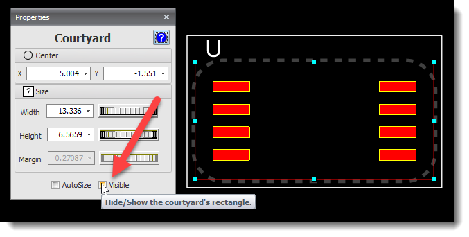
Courtyards

Visible in PCB
 Dim but Visible")
Unselected (Hidden in PCB) Dim but Visible
")
Selected (Hidden in PCB)
Silkscreens

Visible in PCB
")
Unselected (Hidden in PCB)
")
Selected (Hidden in PCB)
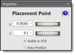
Placement Points

Visible in PCB
")
Unselected (Hidden in PCB)
")
Selected (Hidden in PCB)
August
Friday 29 August 2025
Editing Courtyards
In this video, I’ll explain courtyards in PCB design and show you how to edit them. A courtyard is the area a footprint occupies on the PCB, plus the clearance space around it. It prevents overlaps and is used by the design rule checker and auto layout.

PCB Footprint Courtyards and How to Edit Them
Wednesday 27 August 2025
Reorganized Silkscreen and Courtyard Editor
This makes the flow of design changes from top to bottom more intuitive. Try it!

Silkscreen Editor

Courtyard Editor
Added Show/Hide Parts to the 3D Context Menu (right click)

Radial Context Menu
Quickly Renumber Pads in a Footprint - point and click
Want to renumber pads on a footprint fast? Just click Renumber in the Footprint ribbon tab, then click each pad in the order you want. Each one gets the next number automatically, and the last pad is filled in for you. Super quick, flexible, and easy—give it a try on your own footprint!
Quickly Renumber Pads in a Footprint - point and click
Hide/Show Automatic Silkscreen
Sunday 24 August 2025
Reorder Pads/Devices
You can now reorder by clicking in any of the 4 quadrants of the sort order display.
Why was this added? Simply because it felt natural to let users click on the control to set the sort order.
It wasn’t strictly necessary, and in many traditional approaches you’ll often hear: “if it isn’t broken, don’t fix it.”
But with DEX, the philosophy is different: if there’s a way to make the experience smoother and more intuitive for the user, then go for it. Good design means going beyond “just working” — it’s about making things easier and more enjoyable to use.

Reorder Pads/Devices
Order Pads in a Footprint
Multiple 2D and 3D Viewports
In this video, I’ll show you how DEX lets you view your PCB in 2D and 3D at the same time using multiple viewports. You can easily pan, zoom, and rotate in each view, and even split the 3D view into different layouts—like side by side, one main view with two smaller ones, or a four-way split. These options make it simple to visualize your PCB from every angle, and they make working with your design not just easier—but way more fun!
Multiple 2D and 3D Viewports
Wednesday 13 August 2025
Properties Editors Redesigned
Footprint Placement Point
Courtyard

Courtyard Editor
Silkscreen

Silkscreen Editor
Tuesday 12 August 2025
Multiple 3D Views

Ribbon Commands

Multiple 3D Views
Monday 4 August 2025
3D Model Properties Editor

3D Model Properties Editor
Friday 1 August 2025
Import 3D Into Footprints

Import 3D Into a Footprint
July
Monday 26 July 2025
Faster For Layout
New Splash Screen
Wednesday 23 July 2025
Auto-Panning
Fix panning error for multi-screen computers with non-identical resolutions/text scales. (rare event)
Monday 21 July 2025
Pad Name Sorting
Added Saw-Tooth option. Sorts pads as seen on DIP and SOIC devices.

Pad Name Sorting
Monday 14 July 2025
Docking Panels
Improved sizing, persistence and layout.
Tuesday 8 July 2025
Tooltips and UI Layout
Fix for missing tooltips, and improvements to the user interface layout.Monday 7 July 2025
Extended Tooltips
Extended tooltips added to the 668+ buttons in the Ribbon Menu.
Improved appearance for tooltips.

Extended Tooltips

Turning Tooltips On/Off
June
Monday 30 June 2025
CNC Output
Improved files with comments.
Thursday 26 June 2025
Gerber Files for Panelized PCBs
Fix for copper placement errors with V-Cuts.Sunday 21 June 2025
Minimize Pads

Minimize Pads
Saturday 21 June 2025
Fixed 3D view of auto-minimized pads.
Friday 20 June 2025
Renumber Pads
You can now reorder pad numbers in the Part Editor or the Project Editor (selected device)

Renumbering Pads
Monday 16 June 2025
Fixed Gerber Viewer Layers on/off.
Improved Auto-minimize Pads
Improves routing.

Before

After
Improved Layout for Number Edits with Thumbwheels

Improved Layout for Number Edits with Thumbwheels
Improved text scale for displays

Text Scaling
PCB Panelization
Added interactive controls.Try it!
Improved layout.

PCB Panelization
Saturday 7 June 2025
Non-Circular Inner Pads
Fixed. Can now draw elliptical/rectangular inner pads.
Sunday 1 June 2025
Settings Now Display Units
Also fixed 3 items displaying units only in inches.
Units
May
Saturday 31 May 2025
Grid Now Draws Inside Pad and Via Holes

Grid Now Draws Inside Pad and Via Holes
Tuesday 27 May 2025
Viewport Input Controls
Correct sizing of viewport input controls when text scaled: for instance in 4K viewports.
Saturday 24 May 2025
Adding Rectangles to Schematics and PCBs
Adding Rectangles to Schematics and PCBs
Tuesday 20 May 2025
Improved Text Scaling of ControlsBetter display for displays with text scaling. For example displays 3840x2160 pixels with Scale of 150%
Works great on Apple MacBook Pro M4

Works great on Apple MacBook Pro M4

Text Scalng
DEX on macOS
Friday 16 May 2025
Fix for rotated PCB wrongly clipping the copper pourUpdated Parts Catalog
Friday 2 May 2025
DEX on macOS
This video tutorial demonstrates how to use the PCB designer on macOS. It guides users through starting the application, navigating its interface, and utilizing various features, such as viewing designs in 3-D, accessing schematics, and managing window sizes. The tutorial emphasizes the software's compatibility with macOS and encourages viewers to download DEX for personal use, concluding with wishes for an enjoyable experience using the software.
April
Saturday 26 April 2025
Tuesday 22 April 2025
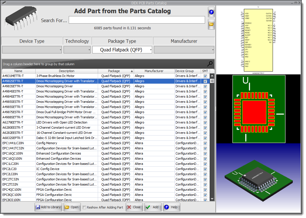
Updated Parts Catalog

Updated Parts Catalog
Tuesday 15 April 2025
Symbol Terminals with OverstrikeFix for font size.

Symbol Terminals with Overstrike
Setting the Height of Selected Text
Works with all text items, including part references, part IDs, symbol terminal value and pad name etc. The same control sets line and border widths.

Setting the Height of Selected Text
Wednesday 9 April 2025
Parts CatalogFix for the footprint value text in 3D being too large.
March
Friday 28 March 2025
Improved fill
Improvements to both linear and radial fill.

Improved Fill
Saturday 22 March 2025
Pen EditorFix for the pen editor sometimes (rarely) updating the wrong entities.
Monday 17 March 2025
Line End Point Manipulator
The line endpoint manipulators are now fixed size of seven pixels.

Color-bar Line Width Thumb-wheel
Improved thumb-wheel scale makes changing the language easier.

Line Width Thumb-wheel
Monday 10 March 2025
Dragging Parts from the LibraryFix for popup dialog saying cannot import SVG.
Monday 10 March 2025
Dragging Parts from the LibraryFix for popup dialog saying cannot import SVG.
Monday 3 March 2025
Minor Bug FixesFix for small internal errors.
February
Saturday 22 February 2025
Bug Fix Internal bug fixes.
Sunday 16 February 2025
Creating a Complex PCB Shape
Have you ever wanted to create a complex PCB shape but found it too tricky with your current PCB design software? Well, check out this video! It’ll show you how to do it.
Creating a Complex PCB Shape
Combining Shapes to Make a PCB
In this video I am going to show you how to create a complex PCB shape by combining several different graphical objects with the current PCB border.
Combining Shapes to Make a PCB
Combing Shapes
I’m going to show you how to combine objects and create a brand-new object. There are three different ways to do this, and I’ll walk you through each one step by step.
Combing Shapes
Saturday 15 February 2025
Graphics
Lines can be line segments or lines with no end/start points.

Line Segment

Line

Setting Line Segment Properties
Adding Arcs
Adding Lines
Thursday 13 February 2025
Dragging Scalable Vector Graphics (SVG) Graphics on to a Graphical Sheet
A SVG graphics is a vector file and produces excellent quality whatever the magnification. Find out more...
A great source of free SVG images is https://www.svgrepo.com/


A Sample SVG Image on a Graphical Sheet
Once placed, the graphics is in a group. Sub-pick to select internal items to edit them.
Note: What appears to be a thick line may be a filled shape with an outline.

Sub-picked and Color Changed

Editing Once Placed
You need to download them first. You can also:
1.Drag them from the website into a Windows Explorer directory. then:
2.Select and drag from the Windows Explorer directory onto a AutoTRAX DEX graphical viewport.
2D Boolean Operation on Entities*
You can now combine several entities into a single entity.
*Does not apply to:
o copper pours

Boolean Operation
 Combine |
 Subtract |
 Intersection |
Sunday 2 February 2025
Combining Shapes to Make a PCB
Combining Shapes to Make a PCB
This video shows you how to create a complex PCB shape by combining several different graphical objects with the current PCB border.
January
Wednesday 25 January 2025
Reflection Surfaces and Shadows in 3D
You can now turn on/off reflective surfaces and shadows. This gives the 3D a different look.

With Shadows and Reflective Surfaces

Without Shadows and Reflective Surfaces
Tuesday 25 January 2025
Bug Fix Removed occasional flashing of number input when adding lines etc.
Monday 24 January 2025
Reflection Surfaces in 3D
You can now turn on/off reflective surfaces.
 Reflective Surfaces Off |
 Reflective Surfaces On |
Bug Fix Fix for footprints that have footprint references way-out of position.
Friday 17 January 2025
Shapes

Shape 3D Selection
Friday 10 January 2025
Compound Curve Shapes
•The PCB Border
•PCB Cutouts
•Copper Pours
•Keepouts
•No Mask Areas
•Pads
•Split Power Planes
Each can be a:
•Rectangle
•Ellipse
•Polygon
•Piecewise Bezier
•Graphics Path (Shape)
You can convert between the shapes using the object's properties editor.

Setting the Shape
Combining Shapes

Add Menu Commands

Combining Two Shapes
You can combine:
•Rectangles
•Ellipses
•Closed curves
•Compound Shapes
oThe PCB Border
oPCB Cutouts
oCopper Pours
oKeepouts
oNo Mask Areas
oPads
Converting Shapes

Converting a Shape
Wednesday 1 January 2025
Improved quality of arc segments in polylines.

KiCad Community Free PartsKiCad Community Free Parts
bugs where via sizes incorrectly sized when manually routing.
•Improved Track Properties Editor.
•Improved Via Default Properties Editor.
Whats New for 2024