You can set your own Electra route command from the Electra Router Settings
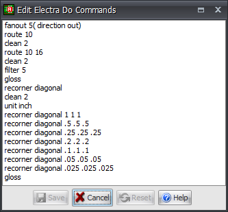
Click on the  button in Electra Router Settings to display the commands as shown below.
Click  to save the Do file. This will then be used on all subsequent Electra routing.
Click the  to reset the commands to the factory settings.
bestsave
bestsave on | off
Controls automatic saving of the best routing solution during a multi-pass routing run. Routing result is saved into a file named “bestsave.rte” at the same location as the design file.
bus
bus [diagonal]
Invokes a “collinear pins” routing pass only on regular array of pins with collinear connections where the pins share a common X or Y coordinate. This is particularly effective on memory arrays. In this mode, the router will not generate conflicts, so rules must allow for sufficient space. By default traces are routed orthogonally, unless the diagonal option is specified.
check
This command can be used to run a DRC (design rules check) and visually tag the violations. This is used in particular when a rule is changed. A check is automatically invoked after every routing pass. The total number of violations is shown on the status line and visual feedback is added to the layout view to indicate conflict locations.
clean
clean [<passes>]
The clean command reroutes all the connections with higher costs settings and helps achieve
•Wire optimization with minimum bends
•Vias minimization
•Less off-center SMD pad entry
•Exit SMD pad on long edge
fan-out
fan-out [<passes>]
[(direction[in_out | in | out])]
[(pin_share [on | off])] [(via_share [on | off])]
{[(pin_type [active | signal | power | unused | all | single])]}
[(max_len <positive_dimension>)]
AutoRoutes short escape wires with a via from SMD pads. Recommended on SMD boards having more than 2 routing layers. Fan-out direction can be set so that fan-out vias are added inside SMD components, and/or outside. Fan-out can be limited by pin type, for example pins connected to power nets only.
Examples:
# 5 fan-out passes
fan-out 5
# Depth for blind & buried vias
fan-out (depth opposite 2) (share_len 500)
5 (pin_type signal) (via_share on)
# Sets via to microvia & grid 25
grid via 25 MICROVIA
# Fan-out using a grid of 25
fan-out (via_grid 25)
filter
filter [<passes>]
At the end of a routing session you may end up with wires/vias in conflicts (crossing or too close to each other), so in order to remove these conflicts the router has to unroute the minimum number of connections that get into conflict, "Filter 5" will do that.
grid
grid [via <positive_value> [<via_id>] |
wire <positive_value> [<layer_name>]
Specifies wire and via grid spacing.
Examples:
# use a routing grid of 8.333
grid wire 8.333
# use a different routing grid 5 on layer 1
grid wire 5 layer 1
limit
limit [cross [<positive_integer> | -1] |
via [<positive_integer> | -1] |
bend [<positive_integer> | -1] |
way [<positive_dimension> | -1]]
The limit command sets absolute limit values to be applied to each connection. Control is provided to limit maximum allowed number of intersecting wire, number of vias per connection, number of bends, and the maximum distance of non preferred (wrong-way) routing. The range of limit for <positive_integer> is 0 through 255. You can set limit values, perform some routing passes, and return to the default system values by executing a limit command with a value of –1. If you don’t supply limit values, computed default values are used by the auto-router.
Examples:
limit via 2
limit way 200
# resets routing limit to default value
limit way –1
lock
lock net <name>
Prevents router from changing or deleting locked wires, Note that the router is not allowed to connect to locked wires.
miter
miter [diagonal] <pin_setback> <slant_setback> <tjunction setback> <bend_<start_setback> <end_setback>>
The miter command charges 90 degree wire corners to 135 degrees. It is performed on wire corners exiting pins and vias, as well as bend and slant wire configuration.
Pin_setback, slant_setback, tjunction and bend_setback options can be used to control which corner type is changed and you can override the default setback values as well:
miter pin .2
miter slant .2
miter bend .2
miter tjunction .2
In comparison to the recorner command, the miter functionality adds control for tjunction and start/end setback value for the bends.
recorner
recorner [diagonal] <pin_setback> <slant_setback> <bend_setback>
The recorner command charges 90 degree wire corners to 135 degrees. It is performed on wire corners exiting pins and vias, as well as bend and slant wire configuration.
Pin_setback, slant_setback and bend_setback options can be used to control which corner type is changed and you can override the default setback values as well:
recorner pin .2
recorner slant .2
recorner bend .2
Pin option is for wires that are connected to pin or via.
Slant is two consecutive 90 degree bends
recorner diagonal .25 .25 .25
You can make multiple calls with decreasing values.
recorner diagonal .50 .50 .50
recorner diagonal .25 .25 .25
recorner diagonal .10 .10 .10
route
route [<passes>[<start_pass>]]
When the number of completed passes (n) is less than 15, the <start_pass> should be n+1.
When the number is higher than 15, then the <start_pass> should be 16.
status_file
Creates a status file with routing history and located in the design directory. The status filename is named after the design name, with the extension .sts.
tax
tax [way | cross | via | off_grid | off_center | side_exit |
squeeze | layer <layer_name>] [<real> | positive_integer>]
This is an alternative method of using the cost command. This is the recommended way to adjust costing. The tax command applies a multiplier to control internal costing. The default value for tax is 1.
write
write [routes | session | script] [<filename>]
Command to save results to a routes file or a session file. The session file provides an integrated file to manage design data and routing data.