Electronic circuit symbols are standardized graphical representations of electronic components used in circuit diagrams and schematics. Each symbol is designed to represent a specific type of component, such as resistors, capacitors, transistors, diodes, and integrated circuits (ICs), and indicates their electrical functionality and connections within the circuit.
These symbols are used to create schematic diagrams, which are visual representations of how components are connected in an electronic circuit. By using these standardized symbols, engineers, technicians, and designers can communicate complex circuit designs in a clear and universally understood manner.
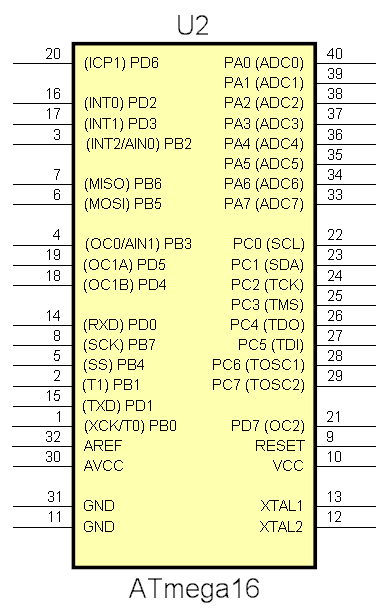 Symbol with border |
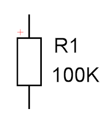 Symbol without border |
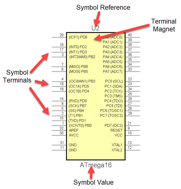
A schematic symbol consists of the following items:
 |
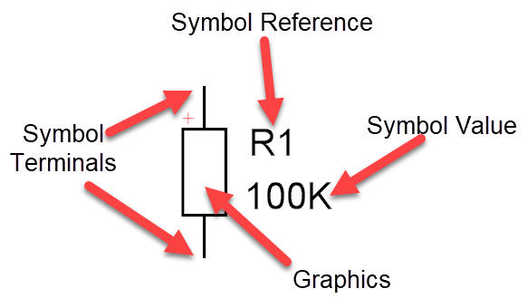 |
Symbol Terminals
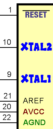
Symbol terminals act as connection points for electrical wires on schematics. A schematic wire connects one or more symbol terminals to either another symbol terminal or another schematic wire.
Symbol References
A symbol reference is a text marker to identify a part. It is used when creating the Bill of Materials for the design (BOM). It is also an important one-to-one link to its footprint in the PCB design.
Symbol Part Values
A symbol value is a text marker to identify a part type. It is used when creating the BOM.
Terminal Magnets
A terminal magnet, shown below, serves as anchor points for symbol terminals.
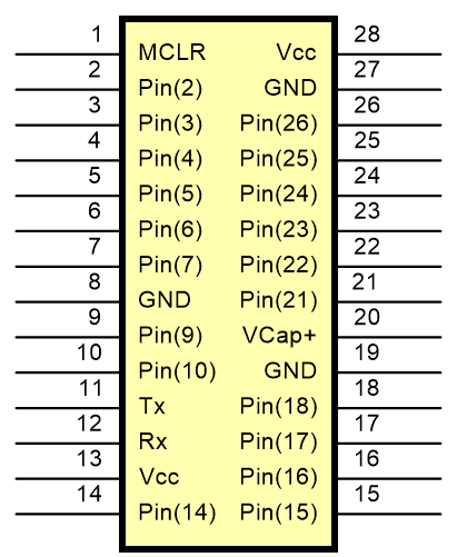
Terminal Magnet (Yellow Rectangle) With Terminals 'Stuck' to the Sides
Symbol Graphics
To show the functionality of a symbol to the viewer, you may need to add graphics that symbolically represent the part.
The Op. Amp graphics shown below are solely for the viewer and represents what the part does: it does not contain any electrical information.
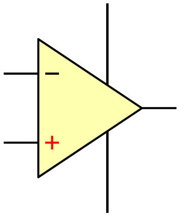
Op-Amp Graphics
No Terminals Added
Here electrical details have been added and viewed in the Part Editor. Some parts of the symbol have been made invisible in schematics so that the symbol appears like the graphics above.
The hidden details are shown semi-transparent in the Part Editor to make it easier for you to design the part.
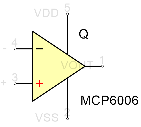
Op-Amp
Terminals Added