You can add any number of oscilloscopes to each of your schematics. You usually will only add one.
You can use a oscilloscopes anywhere in the schematics.
A lab oscilloscope is an electronic instrument used to visualize and analyze the waveform of electrical signals. It displays voltage changes over time on a screen, allowing users to observe the shape, frequency, amplitude, and other characteristics of the signal. Oscilloscopes can measure both analog and digital signals and are essential tools for troubleshooting and designing electronic circuits. They often feature multiple channels, enabling the comparison of different signals, and provide various triggering options for stable waveform capture. Advanced models may include digital storage capabilities, allowing users to save and analyze data for further study.

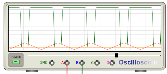
An Oscilloscope
Each oscilloscopes has four input channels labeled A, B, C or D and one ground terminal.
Oscilloscope Properties Editor
Connecting an Oscilloscope to Wires
You must connect the GND terminal ![]() to a circuit ground otherwise the signal traces will not display.
to a circuit ground otherwise the signal traces will not display.
Connect any of the terminals A, B, C or D to schematic wires (nodes) to monitor the signal on those wires.
Turning the Oscilloscope On/Off
 Turn the Power on to start the simulation.
Setting the Trace Color
The color of each track is taken from the line color of the connected schematic wires (node).
Setting the Time-Scale
Drag the slider shown below to the left or to the right to increase or decrease the time-span of the signal being monitored

Drag to Set the Time-Scale

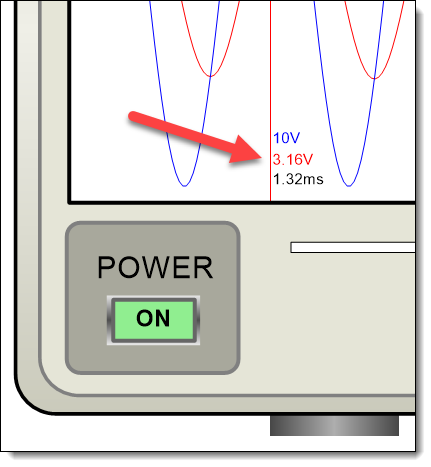
Voltage and Time Values
Showing/Hiding the Grid
Check the ![]() checkbox in the oscilloscope's properties panel to show the grid. Uncheck it, to hide the grid.
checkbox in the oscilloscope's properties panel to show the grid. Uncheck it, to hide the grid.