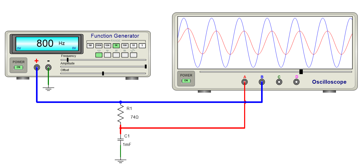
To connect an oscilloscope to wires:
1.Click on one of the four terminals and drag the cursor to a target wire. A new electrical wire will appear and will be auto-routed from the oscilloscope's terminal to the position of the cursor as you move the mouse.
2.Release the left mouse button over a target wire to finish off the connection or press the ESC key to cancel.
NOTE: The colors of the red and blue wires were set by clicking on each of the wires is turn, and clicking on a color button in the Color Bar. The colors of the oscilloscope's traces reflect the color of the associated wires.

An Oscilloscope Connected to Two Wires and a Ground
You must connect the GND terminal ![]() to a circuit ground otherwise the signal traces will not display.
to a circuit ground otherwise the signal traces will not display.
Connect any of the terminals A, B, C or D to schematic wires (nodes) to monitor the signal on those wires.
Turning the Oscilloscope On/Off
 Turn the Power on to start the simulation.
Setting the Trace Color
The color of each track is taken from the line color of the connected schematic wires (node).
Setting the Time-Scale
Drag the slider shown below to the left or to the right to increase or decrease the time-span of the signal being monitored

Drag to Set the Time-Scale

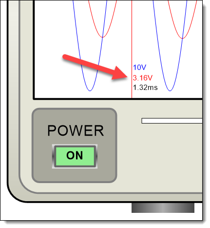
Voltage and Time Values
Showing/Hiding the Grid
Check the ![]() checkbox in the oscilloscope's properties panel to show the grid. Uncheck it, to hide the grid.
checkbox in the oscilloscope's properties panel to show the grid. Uncheck it, to hide the grid.