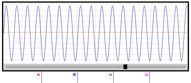
A signal trace is a graphical representation of an electrical signal over time, typically displayed on an oscilloscope or similar visualization tool. It shows how voltage or current changes at a specific point in a circuit, allowing engineers and technicians to analyze the behavior of electronic components and systems. Signal traces can reveal critical information, such as waveform shape, frequency, amplitude, rise and fall times, and potential issues like noise or distortion. By examining these traces, users can troubleshoot problems, verify circuit performance, and ensure proper operation of electronic devices.

A Chart
Chart Instrument Properties Editor