The properties editor for selected symbols is shown below.
It consists of 4 tabs: Properties, Terminals,Footprint,and Spice model.
Properties Tab
The Properties Tab lets you set general properties for the symbol/part.
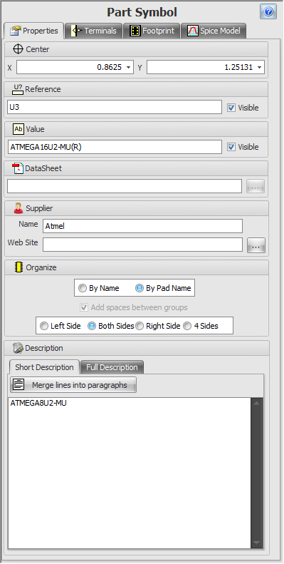
The Properties Tab
The Terminals Tab
The Terminals Tab lists all the symbol terminals and their properties.
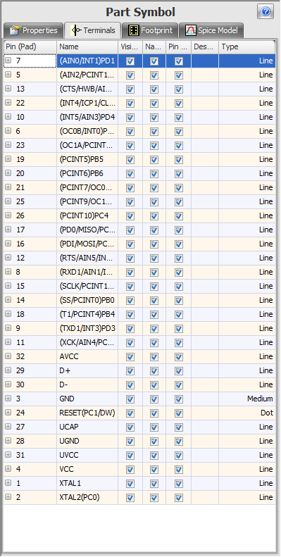
The Terminals Tab
The Footprint Tab
The Footprint Tab displays the properties of the footprint for the selected part.
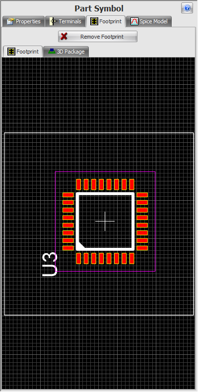
The Footprint Tab
The Spice Model Tab
The Spice Model Tab displays the editable Spice simulation model for the part.
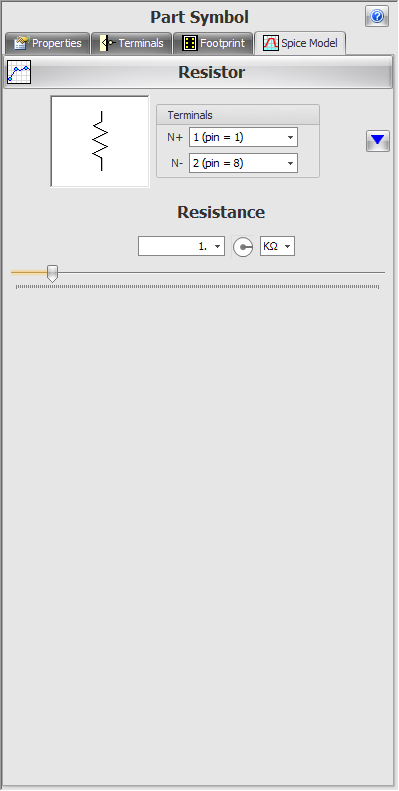
The Spice Model Tab

There are two types of property editor displays: the dockable and the pop-up panel. The Dockable Properties Panel The first one is in the properties panel that is usually displayed on the left. If you cannot see the properties panel either on the left or the right, click on the properties panel button The Popup Properties Panel The second one is a pop-up properties panel which only appears when an object is selected. If you do not see the pop-up properties panel displayed when an object is selected, press the F2 key. Pressing the F2 key toggles the visibility of the pop-up properties panel. You can also press the pop-up button
|
 in the ribbon Panels/Panels button group.

To see what each of the editor's controls does: move the mouse cursor over the control in AutoTRAX DEX (not this help topic) and a popup tooltip will appear. 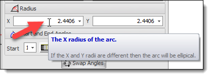 A Typical Popup Tooltip for a Control Can't See the Tooltips? If you cannot see the tooltip: make sure the Show Tooltips check button on the left of the AutoTRAX DEX status bar is 'checked'.  The Show Tooltips Check Button Learning your way around the software. Turning Tooltips On and Off. |