A part consists of a footprint, and optional 3-D model, 1 or more symbols and ideally a data-sheet coupled with hyperlinks to both the supplier and the manufacturer.

Parts
Normally a part consists of just a single symbol, but the part may have 2 or more symbols such as the old TTL devices which have multiple gates and you want a separate symbol for each gate.
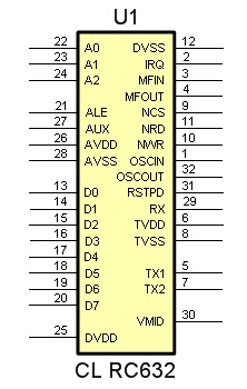
When you start designing a part, the first thing you need to do is find the data-sheet for the part. The data-sheet should define the physical package, the preferred footprint or land pattern and the pin assignment details and what each pin does. Without the parts data-sheet you are flying blind and just guessing as to what you are designing.
So how to find the data-sheet?
In AutoTRAX DEX there are two different types of symbols:
Symbols with terminal magnets.
Fully custom symbols without terminal magnets such as a traditional NPN transistor or an operational amplifier.
Part files contain schematic symbols, text documents and a footprint (land pattern) that contains all the information needed to define the abstract schematic representation for a part together with the footprint required for the PCB and the 3D solid model for the part.
Parts are defined parametrically and this allows a single part to be quickly and easily modified into a different part type. The parametric models define how to create a complete part from only a few simple parameters.
Part= |
 |
+ |
 |
+ |
 |
Schematic Symbol(s) |
|
Footprint |
|
3D Package |