A node connects 2 or more electrical pins together or one or more schematics.
A node can consist of 1 or more wire segments. A wire connected a wire(using a wire junction) or a terminal to another wire via a wire( using a wire junction) or a terminal.
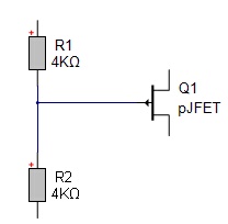
Below is a node consisting of 3 wire segments connecting R1, R2 and Q1.
A terminal can be a
•A Symbol Terminal or
•An Inter-wire Connector or
•A Port.
Symbols consist of zero or more symbol terminals and possibly some graphics to represent the symbol. Symbol terminals can be visible or invisible.
A net defines the physical representation of a node on a PCB and defines which part pins (pads on footprints) are connected together.
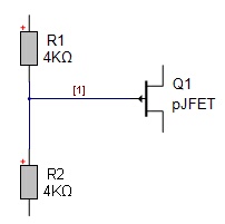
Each node has a node index and an optional node name. By default nodes do not have a node name. Below, the node is shown with the node index displayed. (Use ribbon menu View→Node Names).
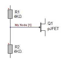
You can set the node name by selecting it by clicking on any of its wires and setting the nodes name using the properties panel. (right-click and select its property panel). Below shows the node after the node's name has been set to 'My Node'.
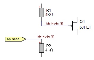
Instead of connecting terminals together with wires you can connect terminals to an inter-wire connector and name the inter-wire connector node by selecting it and setting its name using its property panel. Below the top terminal of R2 and been connected to an inter-wire connector whose name has been set to 'My Node'. This connects R1, R2 and Q1 together. You can place as many inter-wire connectors as you wish on the same schematic or different schematics and all wire connecting to them will be connected together into a single node. The PCB net will then connect all the package pins together.
You can take this to the extreme and connect all terminals to named inter-wire connectors as shown below. Again R1, R2 and Q1are connected together.
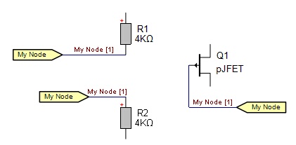
You use inter-wire connectors on the same sheet to reduce wire clutter. You would use them on different schematics to connect wires between sheets. Copy and paste inter-wire connectors works fine.
Ports can also be used to connect wires together on different sheets. Ports let you use a schematic as a sub-system on other sheets.