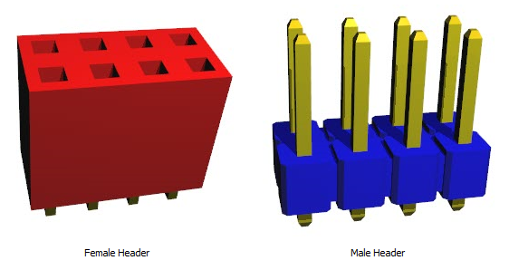
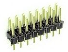
A PCB header is a type of electrical connector that is used as an interface to connect one circuit board to another, or to connect wires or cables to a printed circuit board (PCB). Headers come in many varieties but generally fall under two categories: male headers (also known as "pin headers") which have protruding pins, and female headers (also known as "socket headers") which have receptacles for accepting pins.

Headers

Sockets
Here are some characteristics of PCB headers:
•Design: Headers typically consist of one or more rows of male or female pins that are often spaced 0.1 inches (2.54 mm) apart, although other spacings are also available. The pins are typically housed in a plastic insulator.
•Types: There are several types of PCB headers, including straight (vertical) headers, right-angle headers, shrouded headers, unshrouded headers, breakaway headers (which can be cut to the desired length), and others.
•Number of Pins: Headers can have any number of pins, ranging from just one to several dozen. The number of pins needed depends on the number of signals that need to be transmitted between the connected devices.
•Installation: Headers are typically soldered directly onto the PCB. Wires or other connectors can then be plugged into or onto the header as needed. Some headers are designed to be press-fit into the PCB without the need for solder.
•Applications: Headers are used in a wide variety of applications. They are commonly found in electronics equipment where there is a need for an easy method of connecting and disconnecting components, such as connecting a motherboard to peripheral devices, or for programming and debugging purposes.
Selecting the right header for a given application depends on several factors, including the number of connections needed, the required reliability, the operating environment, and cost considerations. As with all electrical connections, headers must be correctly installed and maintained to ensure reliable operation.
The part builder will automatically create the footprint for the device and also a suitable schematic symbol with the pin names left blank for you to fill in.
 To create a Header part
  button in