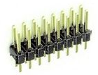
A pin header (or simply header) is a form of electrical connector, often associated with ribbon cable connectors. It consists of one or more rows of pins typically spaced 0.1 inches (2.54 mm) apart, but sometimes 2 millimeters (0.079 in) or 0.05 inches (1.27 mm) is used as well.
 In addition to being used to connect to a ribbon cable connector, pin headers often also function as recipients for jumpers. The most common jumper spacing is 0.1 inches (2.54 mm) spacing, though 2 millimeters (0.079 in) is sometimes used in smaller products.
Pin header connectors are thus "male" connectors (female counterparts do exist, but these are normally just called "header connectors", without "pin") and are mostly used inside equipment, rather than being used as a connector on the outside of the device.
Normally pin headers are pin through hole (PTH) devices, but surface-mount technology (SMT) versions of one and two row pin headers also exist. In the latter case the solder sides of the pins are simply bent on a 90 degree angle so as to be soldered to a solder plane. On single row pin headers the pins are bent alternating to one side or the other, on dual row pin headers the pins are simply bent outwards. If pin headers are optional, the PTH variant is often chosen for ease of manual assembly. Pin headers can be either straight or angled. The latter form is often used to connect two boards together.
 Pin headers are cost-effective due to their simplicity. Headers are often sold as long strips (typically 40 pins for the dual row versions) which can easily be broken off to the right number of pins.
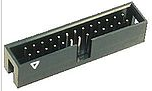
Pin headers with a plastic guide box around them are known as "box headers" or "shrouded headers" and are normally only used in combination with a ribbon cable connector. A notch (key) in the guide box normally prevents placing the connector (polarized by a "bump" on one side) the wrong way around.
In absence of a pin 1 designation on the header, one or more pins in the header may be removed or clipped to indicate a key for correct orientation. If a designation is missing from the header, the PCB may have a marking indicating orientation (often the solder pad around the hole of pin 1 of a PTH header is square rather than round).