In PCB design, the "part reference" or "reference designator" is a label assigned to each component in the design to uniquely identify it. It's a combination of letters and numbers that provides information about the type of component and its sequence in the design.
Here's a deeper dive into the concept of footprint part reference:
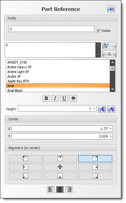
Standard Prefixes
The part reference typically begins with one or two letters that denote the general type or category of the component:
•R: Resistor (e.g., R1, R2, R3...)
•C: Capacitor (e.g., C1, C2, C3...)
•Q: Transistor (e.g., Q1, Q2...)
•U: Integrated Circuit or Module (e.g., U1, U2...)
•L: Inductor or Coil (e.g., L1, L2...)
•D: Diode (including LEDs) (e.g., D1, D2...)
•J: Connector or Jack (e.g., J1, J2...)
... and so on.
•Numbering: Following the letter prefix, there's a unique number which helps distinguish each instance of a particular component type. For example, R1, R2, R3, etc., for resistors, and C1, C2, C3, etc., for capacitors.
•Location on the PCB: The part reference is typically included in the silkscreen layer of the PCB. This ensures that, during assembly and later during testing or repair, each component can be easily identified and located on the board.
•Schematic and Layout Consistency: The part reference on the PCB layout should match its counterpart on the schematic diagram. This consistency is crucial for accurate documentation, troubleshooting, and design modifications.
•Assembly and BOM: The part references are also used in the Bill of Materials (BOM) and assembly instructions. The BOM will list each part reference alongside its associated part number, description, value, and other relevant details.
•Automated Tools: Most modern PCB design software tools will automatically assign part references during the schematic capture phase and will maintain these assignments when the design is transitioned to the layout phase. However, the designer usually has the flexibility to change these assignments as needed.
Best Practices
•It's a good idea to assign part references sequentially, without gaps, to avoid confusion.
•When making design revisions or updates, care should be taken to ensure that part references remain consistent or, if changes are necessary, that all associated documentation is updated accordingly.
•If a PCB has multiple identical modules or sections, some designers use a different set of part references for each module for clarity.
The footprint part reference, though a small detail, plays a significant role in ensuring that a PCB design can be correctly and efficiently manufactured, tested, and serviced throughout its life-cycle.