There are several settings that you can use for creating tracks.
To view the dialog, click on the small button at the bottom right of the Tracks button group. 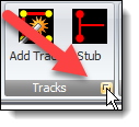
The track settings dialog is shown below.
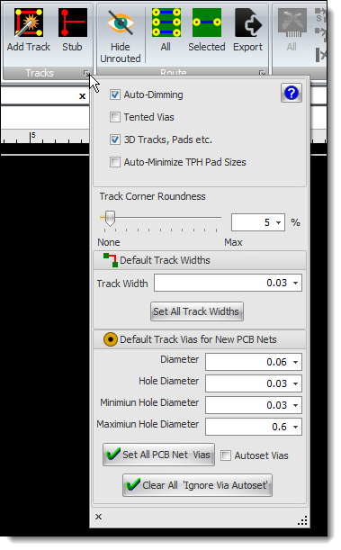
Track Settings Popup
This dialog is also part of the PCB settings in the properties panel.

PCB Settings
Auto-Dimming 
Check this to have automatic dimming when manual routing. Auto dimming will dim non-selected tracks when you are routing a PCB, this makes it easier for you to do the routing.
Tented Vias 
When checked all your vias will be tented.
The role of the PCB’s solder-mask is to protect the copper traces from damage, oxidation, and solder bridging.
This protections also apply to the vias. Tented vias will be more resistant to physical damage and electrical shorts.
If your PCB design has through-hole components that will be wave soldered then a tented via will prevent the solder from flowing up into the via and over the other side of the PCB where it can potentially short out components.
Vias that are also in close proximity to SMT pads should also be tented. This will prevent the solder paste from wicking into the via and creating a poor solder joint.
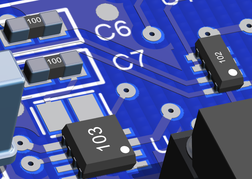
Non-Tented Vias (no solder mask on the vias)
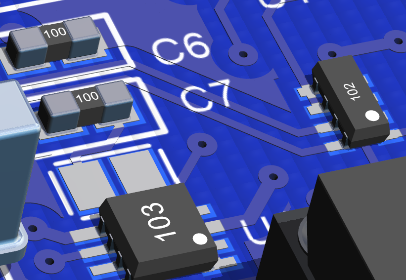
Tented Vias (solder-mask covers the vias)
3D Tracks, Pads etc. 
Check to show true 3D tracks and pads in the 3D viewport. If not checked then tracks and pads are shown as images on the PCB; this speeds up drawing and is useful for slower machine. For the best quality use 3D tracks and pads.
Track Corner Rounding
You can optionally round the corners of all you PCB tracks.
Drag the slider to the right ti increase rounding.
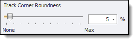
You can also enter the rounding percentage

No rounding
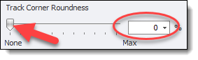

No rounding

100% Rounding

100% Rounding
Default Track Vias
You can set the default track via diameter and the default track via hole diameter.
NOTE: This does not apply to any selected track in the PCB viewport. To change the defaults for a selected track use it's properties panel.
You can also set all track via sizes from the default sizes.

Default Track Vias Settings
Default Track Via Diameter

Default Track Via Diameter
This sets the default via diameter. It is used to set the via diameter for newly created PCB nets. You can override this by editing either the PCB net of the associated schematic node using their respective properties panels.
Default Track Via Hole Diameter

Default Track Via Hole Diameter
This sets the default via hole diameter. It is used to set the via hole diameter for newly created PCB nets. You can override this by editing either the PCB net of the associated schematic node using their respective properties panels.
Minimum Via Hole Diameter

Minimum Via Hole Diameter
This sets the default minimum via hole diameter for new PCB nets.
Maximum Via Hole Diameter

Maximum Via Hole Diameter
This sets the default maximum via hole diameter for new PCB nets.
Setting All Track Via Diameters and Track Via Hole Diameters
Click  to set all track via diameters and hole diameters from the default via diameter and hole diameter. This will also set all net and node all track via diameters and hole diameters.
Autoset Vias
Checking  will force all via diameters to be twice the width of tracks that are attached to it unless the PCB net containing the via has Ignore Via Autoset enabled.
Clear All 'Ignore Via Autoset'
Click the  to turn Ignore Via Autoset off for all PCB nets in the design.
Default Track Width

Default Track Width
You can set the default track width.  It is used to set the via diameter for newly created PCB nets.
Click  to set all track widths from the default track width.