In schematics and symbol schematic: in addition to the user defined snap grid, there is an internal fixed grid that is used for the schematic wire auto-router. This internal fixed grid is called the schematic wiring grid.
Schematics and part symbols schematics are unit-less. That is, the dimensions are not based on imperial or metric units. This is because the schematics are abstract and do not represent physical items. Schematics consist of logical symbols that represent physical parts, in the PCB. These symbols are electrically connected using schematic wires.
To provide rapid auto-routing of the wires connecting the terminals on each symbol, the schematic wiring grid router is used and provides very fast and guaranteed routing between the terminals. It was decided to use a grid of 0.05 inches so that when the schematics are printed the result looks aesthetically pleasing. with the wires not too tightly bunched together. If the metric scale was used, say 1 mm then the wires in the printout would look too densely spaced.

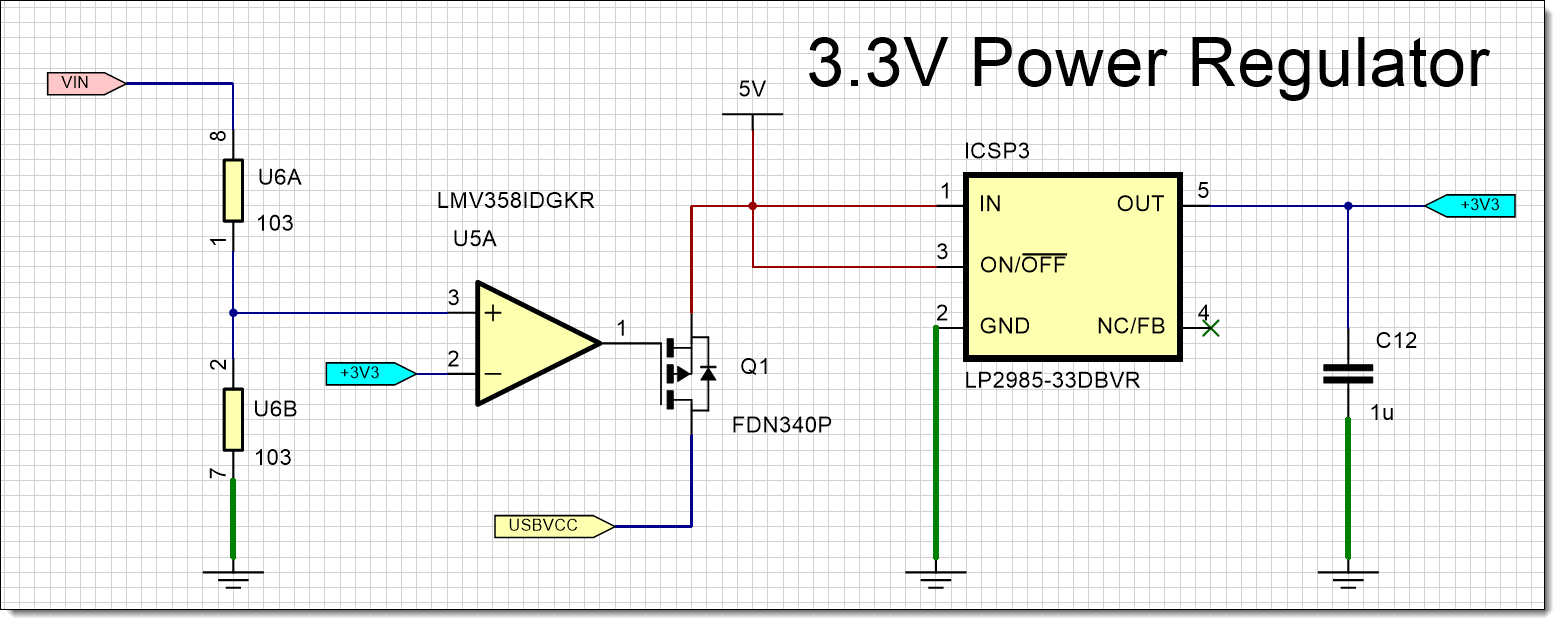
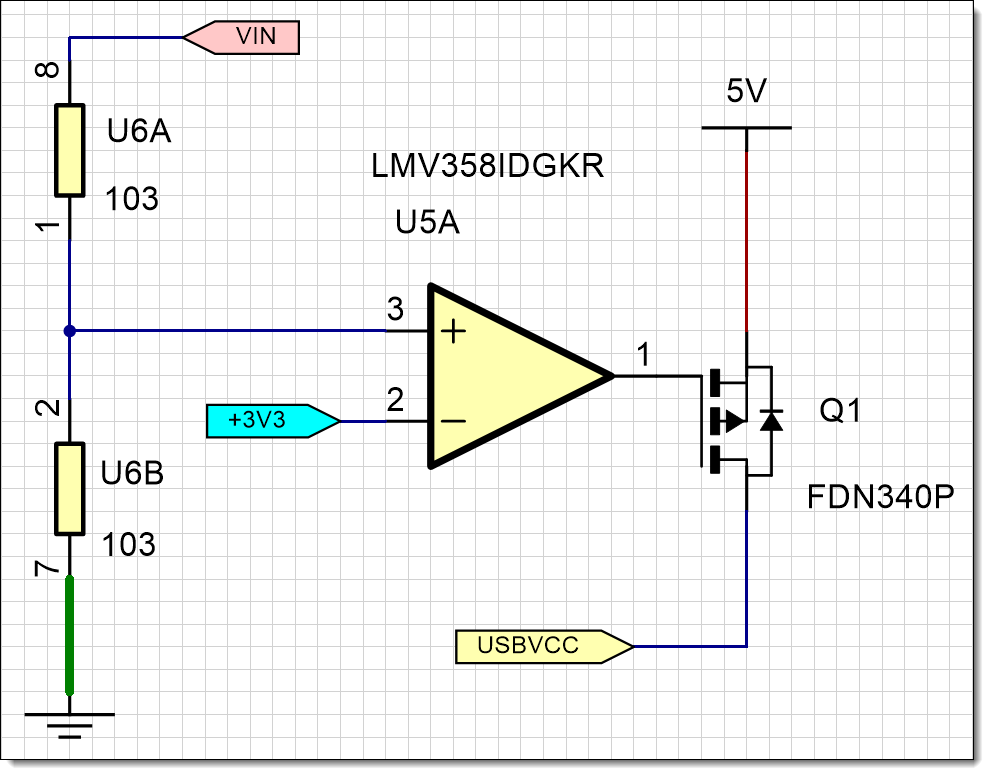
Schematic with a 0.05 Unit Grid
Note: that if the schematic page scale is changed from 1.0 then the density of the wires will obviously change in the printout.
You cannot change the schematic wiring grid as all the library parts are based on a 0.05-inch grid.

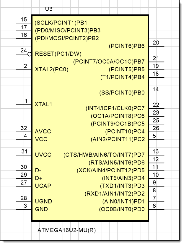
Symbol with No Terminal Magnets and 0.05 Unit Grid
The exception to this 0.05 grid is for terminals attached to terminal magnets. In this case the terminal spacing is based on a 0.1-inch grid as this prevents pin numbers and terminal names from overlapping.

Symbol with Terminal Magnet and 0.1 Unit Grid
When a symbol is moved, it is always snapped to the schematic wiring grid and ensures all the symbol’s terminals are snapped to the schematic wiring grid.
To conclude, wires and terminals always snap to this schematic wiring grid and changing the regular snap spacing and snaps per grid has no effect.
In schematics and symbol design, try not to think about inches or centimeters. Do not change the units or the general snap grid to metric; this will only confuse use. Restrict units to the PCB design and footprint design.
If you are using a schematic for other purposes that does not include adding parts, then you can ignore the schematic wiring grid and use whatever units you wish. The author has used schematics for planning office layout of furniture.