The parts are electrically connected together using schematic wires.
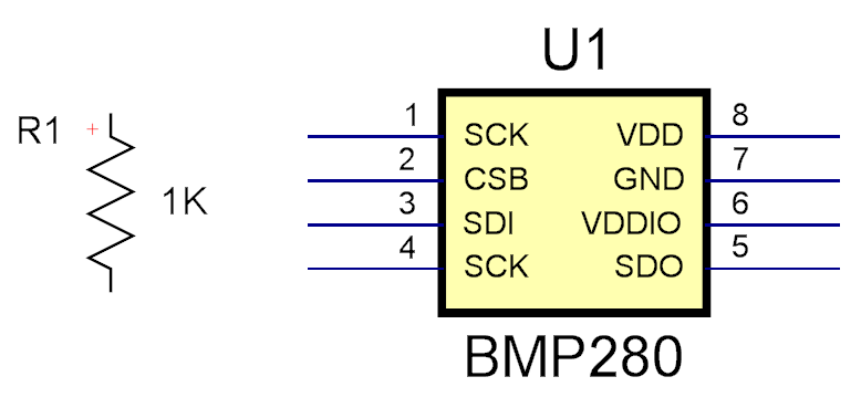
Parts are shown on schematics using schematic part symbols.
A part symbol consists of one or more symbol terminals.
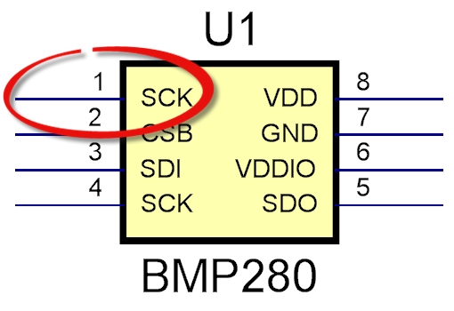
Symbol terminal
The symbol terminals serve as the electrical connection points for the part and schematic wires start and end on symbol terminals.
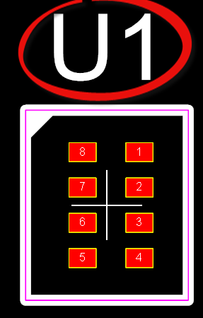
A symbol can optionally have a terminal magnet that is rectangular and serves as the anchor for all the symbol terminals in a part. If you move the symbol terminal is always stays attached to the terminal magnet.
R1 has no terminal magnet while U1 does.
Symbol terminals are always snapped to a 0.05 grid. Since schematics are logical the coordinates are not tied to a measuring system such as inches or cm. However, when it comes to printing the grid is mapped to inches.
A symbol terminal has a name. The name can be set to invisible when it is on a project schematic. It is always visible in the part designer.
Wire connect terminals to each other.
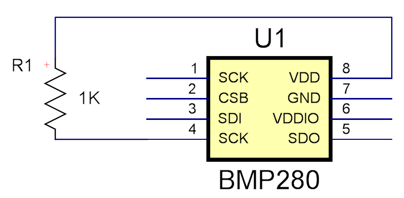
2 parts wired together
All symbols have a symbol reference. This serves to identify the part on the schematic and the PCB and is used in the Bill of Materials (BOM) which lists all the parts used in your design.
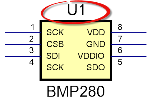
Symbol Reference
There is also Footprint reference on the PCB for the part.