All parametric parts has 1 or more schematic symbols. By default it is a symbol with a rectangular terminal magnet with symbol terminals attached to the left and right edges of the terminal magnet. There will be 1 symbol terminal associated with each pad in the footprint.
Symbols
A part can consist of one or more symbols. Each symbol represents the electrical characteristics of the part and also is the main visualization of the part.
Single Symbol
Below is a single symbol representation of a part using a terminal magnet.
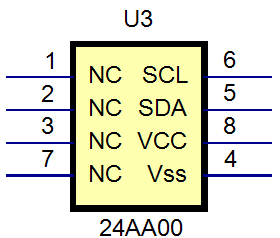
A symbol using a terminal magnet
In contrast to the above we have a single symbol representation of a part not using a terminal magnet. Here the symbol terminals can be placed freely. The graphics are designed to make the functionality of the device clearly visible. In this case an operational amplifier. This is in short contrast to a rectangular representation using a terminal magnet where sometimes the functional to is not clearly visible
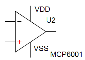
A symbol not using terminal magnet
Multiple Symbols
A part can have more than one symbol. Here you have a symbol that has been represented by 4 different logical get symbols and one power connection symbol using a terminal magnet.

Multiple Symbols for a Single Footprint
Or you can split a symbol as many different symbols as you wish. For instance below the single symbol on the left has been split into five separate symbols whether functionality has been grouped into each symbol. This makes the understanding of the design a lot easier. You can split a symbol into multiple symbols at you have placed a symbol onto a schematic sheet.

The single symbol

Multiple Symbols for the Above Part