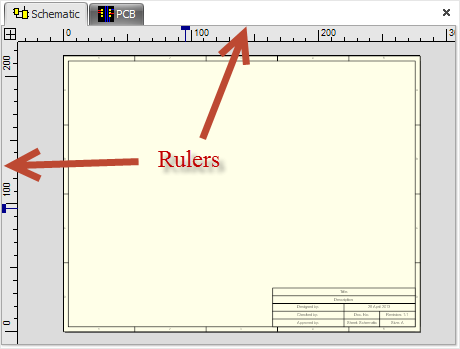
You can optionally display rulers around graphical viewports.By default, schematic to not display a rulers while PCBs do. The rulers act as a measuring device changes when you change units. The rulers also have context menus which contain many useful commands.
As you move your mouse on the viewport you will see both rulers display a line indicating the position of the mouse in the viewport.
At the junction of the two rulers, top left, you will see the origin box. The origin box has a similar context menu to the rulers.
Click the View/Snap→View→ button to view/hide the rulers.
Both the top horizontal ruler and the vertical ruler on the left have context menus. To view the context menu right click on the ruler. The context menus for the horizontal ruler in the vertical ruler shown below. Click on one of the menu items to perform the indicator function.
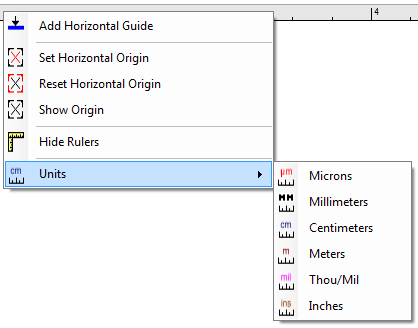
The horizontal rulers context menu
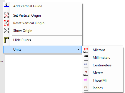
The vertical rulers context menu
Adding Guides
You can add guides to the viewport by dragging from the origin box of the top/left rulers.
Dragging from the left ruler adds a vertical guide to the viewport.
Dragging from the top of ruler adds a vertical guide to the viewport.
Dragging from the origin box adds a point to guide to the viewport.
Setting the Origin
You can set the horizontal or vertical origin or both by selecting the appropriate command in the context menu. Then drag the mouse to where you want the origin to appear and left click to set the new origin. The rulers will update to show the new origin and if you are the grid displayed it will be updated.
Setting The Units
Click on any of the unit menu items to change the units for the current sheet. The rulers will update to show your changes.