"Reflow soldering" is a commonly used method for attaching surface mount components to PCBs and is preferred for manufacturing high volume products or products with many small components.

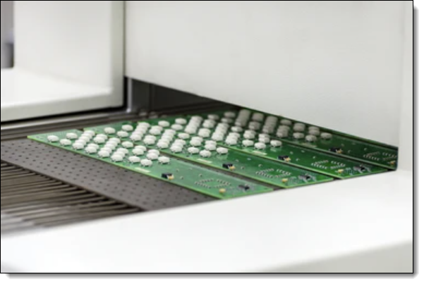
PCB at the output of air convection reflow oven
The term "reflow" comes from the process where the solder is first pasted onto the board in a paste form and then later "reflows" into liquid form during the heating process to make the connection.
Reflow soldering is a process used in the manufacturing of printed circuit boards (PCBs). During this process, solder paste (a mix of solder particles and flux) is applied to the places where components will be mounted on the PCB. The components are then placed on the board, and the entire assembly is heated in a reflow oven.
The goal of reflow soldering is to melt the solder paste, allowing it to flow and create electrical and mechanical connections between the components and the board. The process usually involves several stages or zones:
Preheat Zone
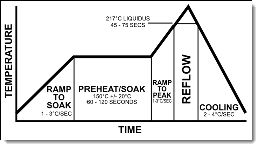
The board and components are gradually heated to a specific temperature range, typically between 150°C to 200°C. This step is done gradually to prevent thermal shock to the components and the board.
Preheating is the initial stage in the reflow soldering process. During this phase, the temperature of the entire board assembly gradually increases towards a designated soak or pre-reflow temperature. The primary objective of the preheating phase is to safely and uniformly elevate the temperature of the assembly to the pre-reflow stage. Additionally, preheating allows the volatile solvents present in the solder paste to be released or "outgas."
To effectively allow solvent expulsion and safely reach pre-reflow temperatures, the PCB should be heated consistently at a linear rate. This rate is often referred to as the temperature slope rate and is commonly measured in degrees Celsius per second (°C/s). The ideal slope rate depends on several variables, including the target processing time, the volatility of the solder paste, and component considerations.
Component considerations often take precedence because many components could crack if the temperature changes too abruptly. The maximum rate of temperature change that the most temperature-sensitive components can tolerate becomes the slope rate's upper limit. However, if the assembly doesn't include thermally sensitive components and the main goal is to maximize throughput, more aggressive slope rates can be applied to expedite processing time. As such, many manufacturers increase the slope rate up to the commonly acceptable maximum of 3.0 °C/s.
On the other hand, if a solder paste with highly volatile solvents is used, excessively fast heating could destabilize the process. When volatile solvents outgas too rapidly, they might cause solder to splatter off the pads and onto the board, leading to solder-balling. This is a primary concern during the preheat phase.
Once the board has been uniformly heated to the target temperature during preheating, the process transitions to the soak or pre-reflow phase.
Thermal Soak Zone
The assembly is kept at a stable temperature to activate the flux in the solder paste, which cleans the component leads and PCB pads to ensure good soldering. This phase also helps to minimize temperature differences across the board, avoiding potential issues related to thermal expansion.
Thermal soak phase is the second stage in the reflow soldering process. This phase typically involves exposing the assembly to heat for 60 to 120 seconds. The heat serves two primary purposes: to dissipate volatile components in the solder paste and to activate the fluxes. Once activated, the fluxes initiate the reduction of oxidation on the leads of the components and the pads.
Maintaining an optimal temperature during this phase is crucial. If the temperature is excessively high, it can cause solder spattering or balling and induce oxidation in the paste, the component terminations, and the attachment pads. Conversely, if the temperature is too low, the fluxes may not fully activate.
The objective at the end of thermal soak zone is to achieve thermal equilibrium across the entire assembly, preparing it for the subsequent reflow zone. Utilizing a soak profile is advised to reduce the temperature difference, or delta T, between components of varying sizes or in cases where the PCB assembly is particularly large. It is also recommended to use a soak profile to minimize voiding in area array type packages.
Reflow Zone
The temperature is increased to the point where the solder paste melts or "reflows." This is typically in the range of 220°C to 245°C, depending on the type of solder paste used. The solder forms a liquidus bond between the component leads and the PCB pads.
The third segment, known as the reflow zone, is also called the "time above reflow" or "temperature above liquidus" (TAL). This is where the process reaches its highest temperature. A key factor to bear in mind is the peak temperature, which is the absolute highest temperature permissible in the whole process. A common peak temperature is 20–40 °C above the liquidus. This maximum limit is set by the component in the assembly with the least resistance to high temperatures, that is, the component most prone to thermal damage. A common practice is to reduce 5 °C from the highest temperature that the most vulnerable component can endure, establishing the process's maximum temperature. Constantly monitoring the process temperature to prevent exceeding this limit is crucial. Moreover, exceedingly high temperatures (beyond 260 °C) can cause damage to the internal dies of SMT components and promote inter-metallic growth. Conversely, a temperature that's not sufficiently high may hinder the adequate reflow of the paste.
The measure of how long the solder remains a liquid is the Time above Liquidus (TAL), or time above reflow. The flux reduces surface tension at the juncture of metals, enabling metallurgical bonding and allowing the individual solder powder spheres to combine. If the profile time surpasses the manufacturer's specification, it may lead to premature flux activation or depletion, which can essentially "dry out" the paste before the solder joint is formed. A deficient time/temperature relationship can reduce the flux's cleaning action, resulting in poor wetting, insufficient solvent and flux removal, and potentially defective solder joints.
Experts generally advise the shortest TAL possible, but most pastes suggest a minimum TAL of 30 seconds, though the rationale behind this specific time isn't apparent. One theory is that there might be areas on the PCB that aren't measured during profiling, and hence, setting the minimum allowable time to 30 seconds lowers the risk of these unmeasured areas not reflowing. A high minimum reflow time also offers a safety margin against changes in oven temperature. Ideally, the wetting time should stay under 60 seconds above liquidus. Excessive time above liquidus may lead to too much inter-metallic growth, resulting in joint brittleness. The board and components might also get damaged with prolonged temperature over liquidus, and most components have a well-defined time limit for exposure to temperatures over a certain maximum. Insufficient time above liquidus may trap solvents and flux, creating the potential for cold or dull joints and solder voids.
Cooling Zone
The assembly is cooled down to solidify the solder joints. The cooling should be controlled to avoid thermal shock and to create a fine grain structure in the solder for the best mechanical strength.
The final zone in the process is a cooling zone, which gradually cools down the treated board to solidify the solder joints. Ensuring proper cooling is essential to prevent excessive inter-metallic creation or thermal shock to the components. The typical temperatures within the cooling zone usually fluctuate between 30–110 °C (86–212 °F). Selecting a quick cooling rate is ideal as it leads to the formation of a fine grain structure, which provides the best mechanical integrity.
While often overlooked, the ramp-down rate is just as important as the maximum ramp-up rate. Above certain temperatures, the ramp rate may not seem crucial, but the maximum permissible slope for any component should be adhered to regardless of whether the component is heating or cooling. A frequently recommended cooling rate is 4 °C/s. This factor should be taken into consideration when evaluating the outcomes of the process.
Thermal Profiling

Example of reflow soldering thermal profile
This is the method of precisely charting or controlling the temperature of the PCB throughout the reflow soldering process. It is critical to ensure that all solder joints on the board reach the appropriate temperatures without overheating any components.
Thermal profiling involves recording temperature readings at various locations on a circuit board to track its thermal journey during the soldering process. In the realm of electronics manufacturing, Statistical Process Control (SPC) is used to assess if the process is being managed effectively, by comparing it against the reflow parameters set by soldering technologies and component specifications.
With advancements in technology, contemporary software tools have made it possible to capture a thermal profile and then automatically optimize it using mathematical simulations. This significantly decreases the time required to define the most effective settings for the process.
Reflow Ovens
A reflow oven is a device primarily utilized for reflow soldering, which involves attaching surface mount electronic components to printed circuit boards (PCBs).
In large-scale commercial applications, reflow ovens are typically long tunnel structures with a conveyor belt that transports PCBs. For prototype development or hobbyist use, PCBs can be inserted into a compact oven with a door.
These commercial conveyor-based reflow ovens have several independently heated zones, each with its own temperature control. As PCBs travel through the oven and its various zones, the speed of the conveyor and temperature of the zones are adjusted to achieve a specific time and temperature profile. The profile used can vary based on the requirements of the PCBs being processed.
Types of Reflow Ovens
Infrared and Convection Ovens
In infrared reflow ovens, ceramic infrared heaters located above and below the conveyor serve as the heat source, radiating heat to the PCBs.

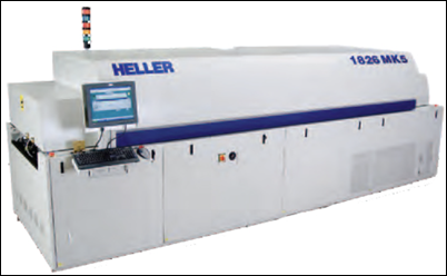
A convection industrial reflow oven
Convection ovens, on the other hand, heat air within chambers and then use this air to transfer heat to the PCBs via convection and conduction. They may have fans to manage the airflow inside the oven. This indirect heating method provides more precise temperature control than direct infrared radiation, as the absorption rate of infrared radiation varies among PCBs and components.
There are ovens that use a combination of both infrared radiative heating and convection heating, and these are referred to as 'infrared convection' ovens.
Some ovens are designed to reflow PCBs in an oxygen-free environment, often using Nitrogen (N2) to achieve this. This approach minimizes the oxidation of solder surfaces. Nitrogen reflow ovens take a few minutes to decrease oxygen concentration within the chamber to acceptable levels, thereby reducing defect rates.
Vapor Phase Oven
In vapor phase ovens, PCBs are heated via thermal energy released during the phase transition (e.g., condensation) of a heat transfer liquid on the PCBs. The liquid selected has a predetermined boiling point to suit the solder alloy being reflowed.
Vapor phase soldering comes with several benefits:
It offers high energy efficiency due to the high heat transfer coefficient of vapor phase media.
The soldering process is oxygen-free, eliminating the need for protective gases like nitrogen.
Overheating of assemblies is avoided. The maximum temperature that assemblies can attain is capped by the boiling point of the medium.
This method is also known as condensation soldering.