AutoTRAX DEX can directly create the CNC files you need to create a PCB.
Printed circuit board milling (also: isolation milling) is the process of removing areas of copper from a sheet of printed circuit board material to recreate the pads, signal traces and structures according to patterns from a digital circuit board plan known as a layout file. Similar to the more common and well known chemical PCB etch process, the PCB milling process is subtractive: material is removed to create the electrical isolation and ground planes required. However, unlike the chemical etch process, PCB milling is typically a non-chemical process and as such it can be completed in a typical office or lab environment without exposure to hazardous chemicals. High quality circuit boards can be produced using either process. In the case of PCB milling, the quality of a circuit board is chiefly determined by the system's true, or weighted, milling accuracy and control as well as the condition (sharpness, temper) of the milling bits and their respective feed/rotational speeds. By contrast, in the chemical etch process, the quality of a circuit board depends on the accuracy and/or quality of the photo-masking and the state of the etching chemicals.
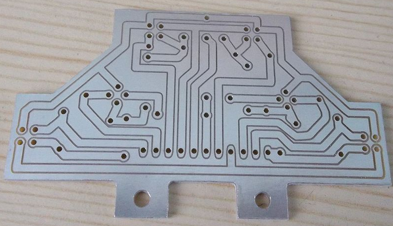
Milled Printed Circuit Board
PCB milling has advantages for both prototyping and also for some specialist PCB designs.
Prototyping can provide a fast-turnaround board production process without the need for wet processing. If a CNC mill is already used for drilling, this single machine can carry out both parts of the process.
Some PCBs, requiring extensive drilling or profiling of the board outline are particularly suitable for production by milling. Where the tracks must precisely follow the board shape, using the same CNC mill for both reduces registration and scaling errors. Many boards that are simple for milling would be almost impossible by wet etching and manual drilling afterwards.
In mass production, milling is unlikely to replace etching although the use of CNC is already standard practice for drilling the boards.
PCB milling system is a single machine that can perform all of the required actions to create a prototype board, with the exception of inserting vias and through hole plating. Most of these machines require only a standard AC mains outlet and a shop-type vacuum cleaner for operation.
he mechanics behind a PCB milling machine are fairly straightforward and have their roots in CNC milling technology. A PCB milling system is similar to a miniature and highly accurate NC milling table. For machine control, positioning information and machine control commands are sent from the controlling software via a serial port or parallel port connection to the milling machine's on-board controller. The controller is then responsible for driving and monitoring the various positioning components which move the milling head and gantry and control the spindle speed. Spindle speeds can range from 30,000 RPM to 100,000 RPM depending on the milling system, with higher spindle speeds equating to better accuracy. Typically this drive system comprises non-monitored stepper motors for the X/Y axis, an on-off non-monitored solenoid or pneumatic piston for the Z-axis, and a DC motor control circuit for spindle speed, none of which provide positional feedback. More advanced systems provide a monitored stepper motor Z-axis drive for greater control during milling and drilling as well as more advanced RF spindle motor control circuits that provide better control over a wider range of speeds.
X and Y axis control
For the X and Y axis drive systems most PCB milling machines use stepper motors that drive a precision lead screw. The lead screw is in turn linked to the gantry or milling head by a special precision machined connection assembly. To maintain correct alignment during milling, the gantry or milling head's direction of travel is guided along using linear or dovetailed bearing(s). Most X/Y drive systems provide user control, via software, of the milling speed, which determines how fast the stepper motors drive their respective axes.
Z axis control
Z axis drive and control are handled in several ways. The first and most common is a simple solenoid that pushes against a spring. When the solenoid is energized it pushes the milling head down against a spring stop which is attached to a pressure foot assembly that limits the milling head's downward travel. The rate of descent as well as the amount of force exerted on the spring stop must be manually set by mechanically adjusting the position of the solenoid's plunger. The second type of Z-axis control is through the use of a pneumatic cylinder - this system functions in the same manner as the solenoid type, pushing against a spring stop/pressure foot assembly. Air for the cylinder is provided by an external compressor with the air flow being controlled by a manually operated regulator and software driven gate valve. Due to the small cylinder size and the amount of air pressure used to drive it there is little range of control between the up and down stops. Both the solenoid and pneumatic system provide no positional feedback while in motion, and are therefore useful for only simple 'up/down' milling tasks. The final type of Z-axis control uses a stepper motor with dynamic positioning feedback. This system allows the milling head to be moved in small accurate steps up or down through its whole range of vertical motion. Further, the speed of these steps can be adjusted to allow tool bits to be eased into the board material rather than hammered into it. The depth (number of steps required) as well as the downward/upward speed is under user control via the controlling software.
Tooling
PCBs may be machined with conventional end-mills, conical d-bit cutters, and spade mills. D-bits and spade mills are cheap and as they have a small point allow the traces to be close together.
Alternatives
A method with similar advantages to mechanical milling is laser etching. Etching PCBs with lasers offers the same advantages as mechanical milling in regards to quick turnaround times, but the nature of the laser etching process is preferable to both milling and chemical etching when it comes to physical variations exerted on the object. Whereas mechanical milling and chemical etching exact physical stress on the board, laser etching offers non-contact surface removal, making it a superior option for PCBs where precision and geometric accuracy are at a premium, such as RF & Microwave designs.