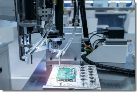
A printed circuit board (PCB) drill file is a type of file used in the manufacturing of PCBs. It contains information about the location and size of all the holes that need to be drilled into the board during the manufacturing process.

PCB Drill Robot
When a PCB design is created, the design software generates a drill file that contains the coordinates and sizes of all the holes required for the PCB. This includes holes for through-hole components, mounting holes, and vias that connect different layers of the board.
The drill file is used by the PCB manufacturer to guide the drilling process. The manufacturer uses a computer-controlled drilling machine to drill the holes into the board according to the specifications in the drill file.
The drill file typically includes information about the size of each hole, the position of the hole on the board, and the layer on which the hole is located. The file may also include information about the type of drill bit to be used for each hole, the drilling speed, and other parameters.
Overall, the drill file is an essential part of the PCB manufacturing process. It ensures that the holes are drilled accurately and precisely, and that the finished PCB meets the specifications of the original design.
Drill Formats
NC format is a set of instructions used by a Numerical Control machine in the manufacturing process. This is typically G-code or a similar language, which defines things like coordinates, tool paths, drilling operations, milling operations, etc.
For PCB manufacturing, different machine manufacturers may use slightly different NC formats, but they all tend to be variants of the G-code language. Common NC files for PCB production include drill files and milling files. These tell the machine where to drill holes, mill slots, etc.
Drill files (Excellon format)
The most common format for PCB drilling data is the Excellon format. It's an industry standard for delivering drilling (and routing) data on PCB fabrication data. Excellon files control CNC drilling machines and are ASCII text based.
Gerber Files
While not strictly an NC format, Gerber is the de-facto standard for PCB industry to define the copper layers, solder mask, legend, and drill and route data. Gerber format files are used to provide information to the machines creating the PCB about where copper needs to be placed or removed.
Milling Files
These are often G-code files that define the paths for milling operations, if those are required.
Remember that the specific formats used can depend on the PCB manufacturer's specific machinery and software. Always consult with your manufacturer to make sure your design files are in a format they can use.