Gerber files are a set of industry-standard file formats used in the manufacturing of printed circuit boards (PCBs). They are used to communicate the design specifications for a PCB to a PCB manufacturer or fabricator.
Gerber files typically include several different files, each of which contains different information about the PCB design. These files include:
•Top layer (or top copper) file: This file contains the pattern for the top layer of copper on the PCB.
•Bottom layer (or bottom copper) file: This file contains the pattern for the bottom layer of copper on the PCB.
•Silkscreen top file: This file contains the markings and labels for the top layer of the PCB.
•Silkscreen bottom file: This file contains the markings and labels for the bottom layer of the PCB.
•Solder mask top file: This file contains the pattern for the solder mask layer on the top side of the PCB.
•Solder mask bottom file: This file contains the pattern for the solder mask layer on the bottom side of the PCB.
•Drill file: This file contains the location and size information for all of the holes drilled into the PCB.
Gerber files are typically created using specialized PCB design software, and are then used by the PCB manufacturer to produce the physical PCB. The manufacturer uses the Gerber files to create the copper layers, silkscreen markings, and solder mask layers on the PCB, as well as to drill the necessary holes.
In summary, Gerber files are a set of industry-standard file formats used to communicate the design specifications for a printed circuit board to a manufacturer. They typically include files for the copper layers, silkscreen markings, solder mask layers, and drill holes.
The Gerber File Format
The Gerber file format is a standard file format used by the printed circuit board (PCB) industry for designing, manufacturing, and testing printed circuit boards. It's a 2D binary vector format that represents the copper layers, solder mask, legend, and drill and route data of a PCB design.
The Gerber file format originated from Gerber Systems Corp., hence the name. Over the years, it has seen a few revisions. The current standard as of my knowledge cutoff in September 2021 is Gerber X2, which is an extension of the previous standard Extended Gerber, or RS-274X.
Here's a little more detail on what each file in a typical Gerber set represents:
•Copper Layers: These files define the conductive areas or traces of the PCB.
•Solder Mask: These files identify where the solder resist will be applied. This coating is typically green and prevents solder bridges from forming between closely spaced solder pads.
•Silkscreen: These files (also known as the Legend), contain the human-readable characters and symbols (like part names and pin numbers) on the PCB.
•Drill Files: These files specify the locations and sizes of the holes to be drilled on the PCB.
•Board Outline: This file defines the physical size and shape of the PCB.
The Gerber file format is widely supported by PCB fabrication houses and is the de facto standard for PCB data exchange. However, as a simple image representation of the PCB data, it doesn't carry any high-level information about the components or the circuit, which is often needed for more advanced manufacturing and assembly processes. This is one of the reasons for the emergence of more advanced file formats such as IPC-2581 and ODB++ that try to address this limitation.
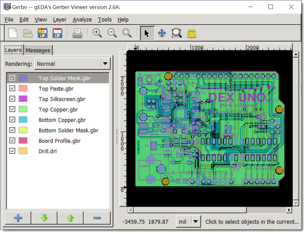
A Free/Open Source Gerber Viewer- gerbv

A Free/Open Source Gerber Viewer- gerbv
Gerbv is an open source Gerber file viewer. Gerber files are standard files used in the electronic industry to communicate the details of printed circuit board (PCB) designs to manufacturing facilities.
Gerbv provides the ability to view, print and do some basic manipulations with these files. It is part of the gEDA project, which is a full GPL'd suite of Electronic Design Automation tools.
As of my knowledge cutoff in September 2021, the tool could handle the Gerber RS-274X format, Excellon drill files, pick and place files, and a few other types.
It's a valuable tool for electronic engineers and anyone involved in the process of PCB manufacturing because it allows for a detailed examination of PCB designs before they are manufactured, potentially catching and correcting errors early in the process.
Ucamco
Ucamco, a company based in Ghent, Belgium, is a global leader in photoplotting and direct imaging systems for PCB (Printed Circuit Board) fabrication. They also develop software solutions for the PCB industry, including communication tools and quality control equipment.
One of their significant contributions to the PCB industry is the maintenance and development of the Gerber file format. The Gerber file format is a widely used, standard file format for communicating PCB design information to manufacturing. It is used to represent the copper layers, solder mask, legend, and drill and rout data in 2D images.
Originally, the Gerber format was a proprietary format developed by Gerber Systems Corp., but it has since been developed into an open ASCII vector format by Ucamco, which took over maintenance of the Gerber format. The latest version as of my last update in 2021 is the Extended Gerber, or RS-274X, which includes embedded aperture information, making it a more complete and less error-prone file format for PCB production.
Ucamco also defined the Gerber Job file format, which is a JSON-based file format for exchanging PCB job parameters. This complements the Gerber image format by providing a way to package all the parameters for a PCB job into one file.
For more recent information, it would be best to visit https: //www.ucamco.com/ or reach out to them directly.
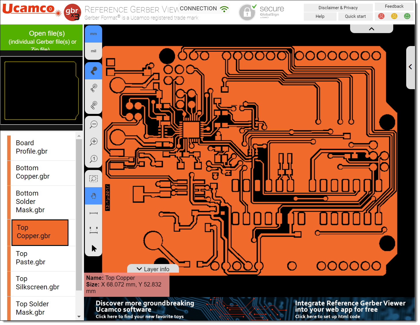
The Free Ucamco Gerber Reference Viewer

The Free Ucamco Gerber Reference Viewer
Open Free Ucamco Gerber Reference Viewer...
The Gerber RS-274X File Format
RS-274X, also known as Extended Gerber or X-Gerber, is the most widely used standard for data exchange in PCB manufacturing. It's an extension of the original Gerber format, RS-274-D, also known as Standard Gerber or just Gerber.
RS-274X introduced a number of key improvements over the original format. While Standard Gerber required a separate aperture file to interpret the design information, RS-274X embeds the aperture information into the file itself, making the format self-contained and less prone to errors and confusion. This was a huge benefit and made the format more reliable and easier to use.
In an Extended Gerber file, each line of code corresponds to a command for a photo-plotter, a machine that uses light to draw an image onto a photosensitive material. The commands include things like:
•"Move to coordinates X,Y"
•"Draw a line to coordinates X,Y"
•"Flash (draw) an aperture (shape)"
•"Interpolate a circle or arc with a specific radius to coordinates X,Y"
These commands collectively describe all of the shapes and patterns on the individual layers of a PCB.
RS-274X also allows for the definition of custom apertures, providing designers with much more flexibility in their designs. It also introduces the ability to specify polarity (dark or clear) for each shape, allowing for the creation of negative images.
Despite being an older format, Extended Gerber is still widely used and is accepted by virtually all PCB manufacturers. However, as mentioned before, more advanced formats like Gerber X2, IPC-2581, and ODB++ are increasingly used due to their ability to convey more complex design information.
The Gerber X3 File Format
Introduced in 2020, Gerber X3 stands as a leading data file format for the transfer of printed circuit board (PCB) design data. It has gained acceptance as a default standard due to its inclusion of both PCB layout data along with the Bill of Materials (BOM) and Component Placement List (CPL) data in one comprehensive and easily accessible file format.
The Gerber X3 standard expands its capabilities by incorporating component data within the Gerber data. This includes geometric data such as the centroid, outline, fiducial locations, and footprints, all of which can naturally fit into a Gerber image file.
The major benefit of combining raw board data and component data in Gerber files is the ability to holistically review the final board. This results in a streamlined work-flow, facilitating the transfer of component information from the Computer-Aided Design (CAD) system to the Assembly Computer-Aided Manufacturing (CAM) system.
The key advantage here is the unification of data into a single format that can be easily imported, analyzed, and visualized by the CAM system. This allows for the automatic generation of outputs for various assembly equipment, leading to significant time and cost savings.
Maintaining the tradition of the original Gerber format, X3 is a straightforward, human-readable ASCII format. This enables engineers to quickly identify and rectify any anomalies. Additionally, Gerber X3 ensures backward compatibility, allowing users of older systems to read and use its data, albeit limited to features supported by their current system.
Gerber X3 files incorporate a new data set known as Component Layers (Top & Bottom). Within this set, there are dedicated attributes for components where all necessary information about each component on every layer can be defined. This further enhances the format's capability and utility in PCB design.