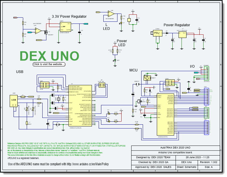
A Typical Schematic Sheet
Printed design schematics are a type of visual representation used by designers and engineers in order to capture the details of their designs. A schematic typically includes components and how they are connected, as well as electrical connections between various parts. Schematics can be either hand-drawn or computer-generated. Hand-drawn schematics are generally more precise and accurate than those generated by computer software, though they require more time and effort to create. Computer-generated schematics are often easier to read due to the use of standardized symbols, but may lack detail which is necessary for complex designs. In either case, printed design schematics help to communicate complex information quickly and accurately.
Designers use printed design schematics for a variety of purposes. They can be used to plan out a system or device from start to finish, map out individual components or circuit boards, or troubleshoot existing systems. Many types of equipment such as computers and other electronic devices rely on these schematics in order to operate correctly. When designing an item from scratch, a designer may lay out all the needed components before actually assembling them into one unit. This helps reduce errors that could occur during assembly if the designer had not planned each step carefully beforehand.
The use of printed design schematics also facilitates communication between different parties involved in the project such as engineers, technicians, fabricators and other people who need to understand the plans in order to perform their respective tasks properly. Having a clear diagram of what needs to be done makes it easier for everyone involved to cooperate efficiently and ensure that the end product meets all specifications required for its intended purpose.
Schematic diagrams also provide invaluable insights into how various devices function when assembled together by showing exactly which components interact with each other at a given point in time. Knowing these connections can assist technicians in diagnosing any issues with a system more easily without having to guess as much about how it works internally. Printed design schematics therefore serve as essential tools for both designers and technicians alike when it comes to creating new products and troubleshooting existing ones with efficiency and accuracy.