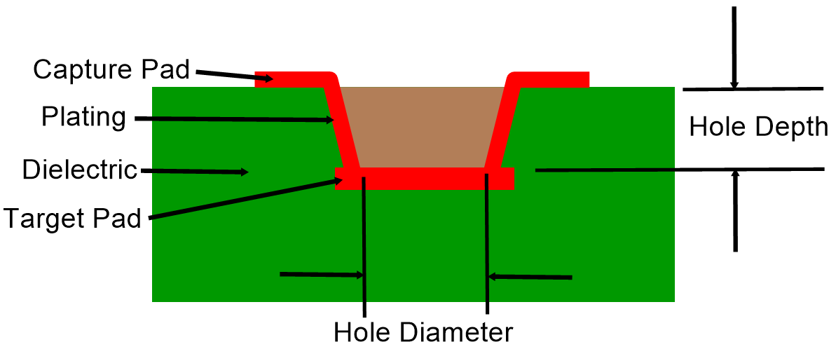
Recommended microvia sizes can vary depending on factors such as the specific PCB design requirements, the manufacturing capabilities of the PCB manufacturer, the technology used (laser drilling or mechanical drilling), and the application's performance needs. However, here are some general guidelines for microvia sizes:
Diameter
For laser-drilled microvias: Microvia diameters typically range from around 100 micrometers (μm) to 250 μm. Smaller diameters are possible with advanced laser drilling technology.
For mechanically drilled microvias: Microvia diameters may be slightly larger due to the capabilities of mechanical drills. Diameters around 150 μm to 300 μm could be common.
Aspect Ratio
The aspect ratio (depth-to-diameter ratio) of microvias can vary, but a typical range is around 0.8 to 1.2. Some advanced manufacturing techniques may allow for higher aspect ratios.
The Microvia aspect ratio = hole depth / hole diameter
Pitch and Pad Size
The pitch (spacing between adjacent microvias) and pad size (landing area for the microvia) are important considerations to prevent electrical and thermal issues. A typical pitch could be around 200 μm to 300 μm, and the pad size should accommodate the microvia diameter while providing sufficient room for plating and reliability.
Annular Ring
The annular ring is the copper pad area around the microvia hole. A recommended annular ring size could be around 75 μm to 125 μm to ensure proper plating and reliability.
Spacing and Clearance
Maintain proper spacing and clearance between microvias, traces, and components to prevent signal interference and avoid manufacturing issues.
Design Constraints
The specific design constraints, such as the number of layers, the thickness of build-up layers, the material used, and the desired performance characteristics, will influence the recommended microvia sizes.
Signal Integrity and High Frequencies
For high-speed and high-frequency applications, consult signal integrity guidelines and impedance control calculations to determine appropriate microvia dimensions.
It's important to note that the above guidelines are general recommendations and may not be suitable for all situations. Designers should work closely with their chosen PCB manufacturer and consider the specific needs of their project to determine the optimal microvia sizes. Additionally, as PCB manufacturing technology advances, smaller microvia sizes and higher aspect ratios may become more feasible.

Microvia
Always follow the design rules and capabilities provided by the PCB manufacturer to ensure successful fabrication and reliable performance of your PCB with microvias.